GRX-Q - Magnetic-inductive flow measurement
In magnetic-inductive flow measurement (MID), an electrical voltage is generated by the interaction between the flow velocity of a liquid and a magnetic field. This principle is based on Faraday's law of induction, according to which an electrical field strength arises due to an electrically conductive liquid flowing through a magnetic field.
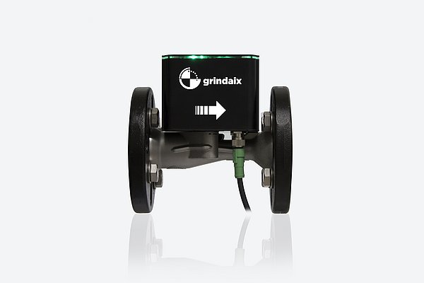
The medium flows through a pipe with an insulated lining. Two diametrically opposed electrodes are mounted on the pipe wall perpendicular to the magnetic field and the direction of flow (see Fig. 2-14). The voltage tapped across the electrodes is proportional to the average flow velocity. A transmitter is used to separate the useful signal from the much larger interference signal. To minimize measurement errors, the fluid flow must be laminar. To achieve this, a stabilizing section of three to five times the pipe diameter should be provided. This must also be observed for previous cross-section changes and bends.
The electrodes should be made of corrosion-resistant material, as they are in direct contact with the medium to be measured.
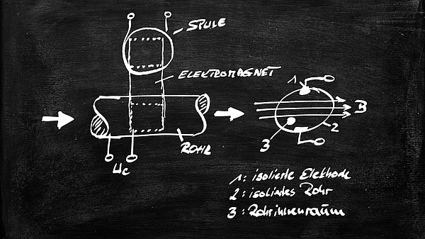
The type of signal processing is determined by the field excitation (DC or AC field). An electrochemical polarization of the electrodes is prevented by AC fields. The physical basis is based on the Lorentz field strength E (Eq. 2-20).
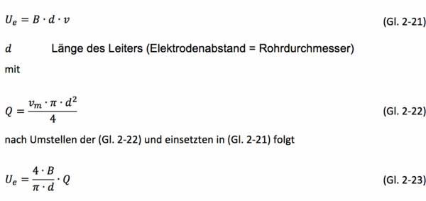
With Ue=E∙d, provided that the velocity v is orthogonal to the direction of the field B, the equation (Eq. 2-21) follows:
From the (Eq. 2-23) it can be seen that the voltage Ue is proportional to the volume flow rate Q. Although the electrical conductivity of the medium is not part of the equation, it must not fall below a lower limit of approx. 100 µS/m. At a lower conductivity, the measuring voltage Ue can collapse when the system is loaded through the input resistance of the measuring amplifier.
The advantages of this measuring principle are that it is independent of the physical properties of the medium, such as pressure, temperature and viscosity. In addition, the system is practically wear and maintenance-free, since no mechanically moving parts are used. The method is well suited for measuring contaminated liquids such as slurries or solids. In addition, no additional pressure loss is caused by an internal measuring body or a cross-sectional constriction. The analog output signal also exhibits good linearity over a wide dynamic range.
However, the measuring principle can only be applied to electrically conductive liquids. Furthermore, deposits in the measuring tube can cause a narrowing of the cross-section, leading to measurement errors. The temperature restrictions and the minimum flow rate (up to 250 °C, min 0.5 m/s) should also be mentioned as disadvantages.
Products relevant to this article:
GRX-Q
You may also be interested in these articles from our magazine:
Frequent problems during grinding
Although grinding is a widely used manufacturing process, it is nevertheless complex and carries the risk of making mistakes in many places. In all cases, these have an impact on efficiency and component quality. Read on to find out what needs to be taken into account in detail and what the most common errors in grinding actually are.
GRX-Q - Flowed bodies
In this type of flow measurement, flow is applied to floating bodies, spring disks or flaps. After the differential pressure method, variable area flow measurement is one of the most frequently used methods.
GRX-Q - Displacement meter
With the displacement meters, the moving measuring walls are driven by the medium to be measured. The movement is recorded and counted.
GRX-Q - Ultrasonic flow measurement
Ultrasonic flow measurement, also known as the transmission principle, works on the basis of the propagation speed of sound waves, which changes in moving liquids with the flow speed of the transmission medium.
