Coolant lubricant filtration systems - it all comes down to µm!
Filtration systems are used in many areas of industrial production. The tasks, functions and influences of a filtration system for cooling lubricants in modern and efficient industrial production with CNC machine tools are extremely varied and by no means trivial.
Cooling lubricant filtration systems filter contaminants from the liquid cooling lubricant medium. This is a solid-liquid separation process in which solid contamination particles, e.g. machining residues or chips, are filtered out of the cooling lubricant. Very high filtration grades are sometimes required for cooling lubricant filtration (e.g. NAS 08), so that even the smallest particles must be reliably filtered out of the cooling lubricant. The cooling lubricant filtration system therefore fulfills the task of supplying the production process on one or more CNC machine tools with sufficiently prepared cooling lubricant that has sufficient cooling lubricant purity for the machining task. Coolant lubricant cleaning also significantly extends the service life of the coolant lubricant, meaning that the coolant lubricant needs to be replaced less frequently.
There are various ways to implement the cooling lubricant filtration system in the cooling lubricant systems.
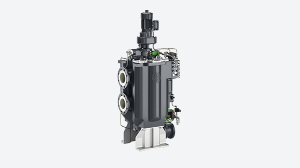
Integration of the cooling lubricant filtration system into the cooling lubricant supply system
Individual system:
Individual systems are used when only individual processing machines or small machine groups (< 3 machines) are connected to the cooling lubricant filtration system.
Individual systems are generally used when different processing methods or materials are used within a production area. This means that the cooling lubricant filtration systems can be individually adapted to the requirements of the various filtration tasks.
Central system:
Central systems are used when the cooling lubricant filtration systems supply an entire production area (> 3 machines).
Centralized systems are preferable to individual systems if similar processing methods and materials are used in a production area. They generally work more economically (reduction in the number of pumps), often achieve better filtration results and require less space than the total installation area of the individual systems.
Main flow:
In main flow operation, the cooling lubricant filtration system is connected directly to the cooling lubricant supply of the processing machine. As the two systems are not decoupled from each other, the other cannot continue to operate if one of the two components fails. The cooling lubricant provided for machining is 100% filtered before use.
Full flow:
Full-flow operation has become established in practice. Here, the entire quantity of cooling lubricant is cleaned. At the same time, the processing machine is decoupled from the filtration system by an emergency supply. This ensures a stable supply even if the system fails. To achieve this, the cooling lubricant filtration is operated in a separate circuit, which cleans around 10% more cooling lubricant than is required by the connected processing machines.
Partial flow:
In partial flow operation (also known as bypass operation), the cooling lubricant filtration system is operated in a circuit that is decoupled from the main circuit and connected in parallel. This means that the cooling lubricant can be cleaned independently of the processing machines. However, only part (approx. 10-20%) of the total coolant lubricant quantity is cleaned, which results in an increased level of contamination in the coolant lubricant. In addition, a large proportion of the contamination is only removed from the cooling lubricant circuit after it has been circulated several times.
Filtration processes and systems
During sedimentation, the contaminated cooling lubricant is placed in a container in which the dirt particles settle on the bottom of the container due to the influence of gravity. The cleaned cooling lubricant can be removed from the surface. The deposited contamination particles can be removed from the bottom manually or automatically using a scraper belt conveyor.
Advantages:
+ low investment costs
+ low energy consumption
+ no consumption of filter aids
Disadvantages:
- High residual moisture of the dirt discharge
- low purity achievable
- high space requirement
During centrifuging, the contaminated cooling lubricant is fed into a rotating drum. The centrifugal forces that occur separate the cooling lubricant from the dirt particles. Centrifuges for coolant lubricant cleaning can be designed as disk separators, hydrocyclones, solid bowl centrifuges or chamber separators.
Advantages:
+ No consumption of filter aids
+ high purity achievable
+ Low space requirement
+ even small particles can be separated
Disadvantages:
- Relatively high investment costs
- high energy consumption
- low capacity (volume flow)
- cannot be used with chip wool
During magnetic separation, the contaminated cooling lubricant is guided past magnets, whereby the metallic, magnetic machining residues are discharged from the cooling lubricant.
Advantages:
+ No consumption of filter aids
Disadvantages:
- high purity cannot be achieved
- only magnetic dirt particles can be removed
- no discharge of grinding wheel abrasion possible
Filtration
The cooling lubricant is passed through a porous filter medium. The cooling lubricant can pass through this, but the contaminants are retained and the cooling lubricant is thus cleaned. Filtration systems can be designed as belt filters, drum filters, cartridge filters or precoat filters.
Filters with screen cartridge inserts are also suitable as a supplement to an existing filtration system in the form of additional filtration due to their low space requirement and very good cleaning performance.
Due to the wide range of influencing factors in cooling lubricant filtration, the cooling lubricant filtration system must be selected on the basis of a detailed examination of the process and discussion of the various options. This is the only way to find the optimum solution for the customer from a technical, economic and ecological point of view.
Our recommendation
A filtration solution is optimal if it combines a filtration performance that meets requirements with low operating costs. We have had particularly positive experiences with protective filters with replaceable and backwashable fabric filter cartridges. These protective filters require little installation space, monitor and backwash fully automatically and also achieve a high filtration performance (up to 20µm).
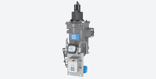
Purity classes for cooling lubricants
The purity of cooling lubricants is described using so-called purity classes. This enables flawless technical communication about the cooling lubricant purity and the requirements of the machining task for the cooling lubricant can be clearly identified and classified in advance. The requirements for the coolant lubricant purity vary from process to process. The most demanding processes from the point of view of cooling lubricant purity are honing and lapping with a maximum permissible particle size of 2 µm. In addition, a certain minimum level of purity must be maintained in order for many components within the cooling lubricant system (e.g. pumps, valves) to operate properly.
The purity of cooling lubricants can be described using two common standards, which are described below:
Cooling lubricant purity according to NAS 1638
The abbreviation NAS refers to the National Aerospace Standard. NAS 1638 describes the number of solid dirt particles of certain sizes in a liquid. For categorization, the NAS standard uses a coding that defines the permissible number of particles of a certain size in a sample of 100 ml of liquid. According to NAS, five size classes are formed: 5-15 µm, 15-25 µm, 25-50 µm, 50-100 µm and >100 µm. The frequencies of these particle sizes are not counted cumulatively but differentially.
Example:
NAS 5: max. 8000 particles of size 5-15 µm, max. 1425 particles of size
15-25 µm, max. 253 particles of size 25-50 µm, max. 45 particles of size
50-100 µm and max. 8 particles of size > 100 µm in 100 ml cooling lubricant.
Cooling lubricant purity according to ISO 4406
Similar to NAS 1638, the ISO 4406 standard specifies the permissible frequency of dirt particles of certain sizes in 100 ml of cooling lubricant. For this purpose, a division is made into three size ranges: >4µm, >6µm and >14µm. The frequency of the dirt particles is determined cumulatively for the individual ranges. Similar to NAS 1638, ISO 4406 also uses a coding system. The purity is indicated by ordinal numbers divided by slashes. The first ordinal number indicates the quantity range of dirt particles >4µm, the second that of dirt particles >6µm and the third that of particles >14µm.
Example:
DIN ISO 20/17/13: 500,000-1,000,000 particles >4 μm, 64,000-130,000 particles >6 μm and 4,000-8,000 particles >14 μm in 100 ml cooling lubricant
Influences of cooling lubricant filtration on production
The purity of the cooling lubricant has a decisive influence on production, which will be explained below using a few examples.
Machining quality
In order to achieve the required surface quality (Rz, Ra) during ultra-fine machining (e.g. grinding), the cooling lubricant must have an appropriate level of purity. Depending on the required surface quality, appropriate filtration must be used. The required degree of purity is usually divided into ultra-fine, fine, medium and coarse. A direct and reliable correlation between the coolant purity and the negative influence on the achievable surface quality during grinding does not yet exist.
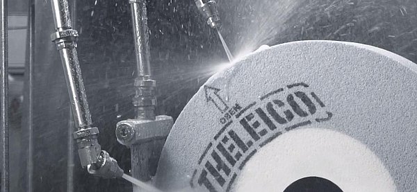
Component wear in the cooling lubricant system
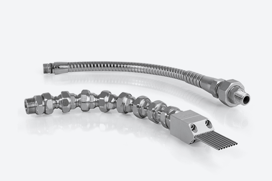
The entrained dirt particles not only have an influence on component production, but also have a significant impact on the service life of system components. The dirt particles cause abrasive wear on the components and units of the cooling lubricant system. This affects pumps, valves, cooling lubricant coolers, but also lubricoolant pipes and pipelines, which can become clogged if the flow rate is too low due to sediment formation inside the pipe. Clogging with machining residues can also occur in cooling lubricant nozzles. Reliable cooling lubricant filtration is therefore crucial for reliable and efficient operation of the entire cooling lubricant system. Inadequate cleaning performance can result in high costs due to the regular replacement of expensive cooling lubricant system components as a result of wear and tear, or even the failure of the cooling lubricant filtration system or a machine tool.
Incorrect dimensioning
In order to correctly design a cooling lubricant filtration system, a number of relevant variables must be known. These relate to the inlet, the so-called unfiltrate and the outlet (filtrate). Relevant parameters are:
Cooling lubricant:
Flow rate, type, viscosity, additives used
Contamination:
Dirt input/quantity, materials used, machining process and parameters
Purity:
Absolute filter fineness, degree of purity (NAS 1638 or ISO 4406)
In the event of incorrect dimensioning, the cooling lubricant filtration system may no longer be able to achieve the required purity of the cooling lubricant. The insufficiently filtered cooling lubricant causes abrasive wear on sensitive and expensive cooling lubricant system components such as pumps and valves on the pure cooling lubricant side. Oversized cooling lubricant filtration is also unsuitable due to the large amount of space, energy and investment required.
Impermissible changes to the process parameters
If the process parameters of an existing cooling lubricant filtration system are changed to an impermissibly large extent, the filtration performance can be significantly impaired. This can occur, for example, if more processing machines are connected to a filtration system than originally planned in the dimensioning phase. The lubricoolant filtration system, which is then too small, can no longer filter out the dirt load supplied.
Problems can also occur if components in the lubricoolant system are replaced and the required lubricoolant purity increases, e.g. when a pump is changed. As a result, the new component wears out faster than expected.
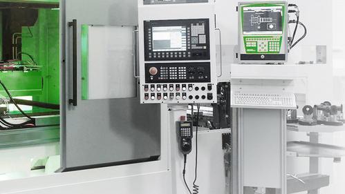
Optimization of cooling lubricant filtration systems
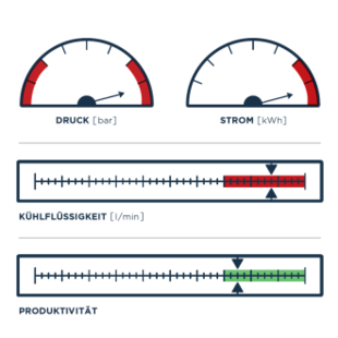
In most cases, small changes or conversions at the right point in the filtration system are enough to significantly increase the cleaning performance. However, determining these optimized process parameters is by no means trivial.
Have you been wondering for some time whether your cooling lubricant filtration system is still working reliably and efficiently with the desired filtration performance? We can find out for you! Team Grindaix is your experienced cooling lubricant system service provider with extensive experience in optimizing cooling lubricant filtration systems. Our standardized system analysis enables us to quickly identify potential for optimizing your filtration system. For existing systems, we also check the current efficiency and cleaning performance. We are also happy to support you in the planning of your new filtration system, e.g. when building a new factory.
Summary
Cooling lubricant filtration systems are directly involved in the success of the machining task on CNC machine tools. The technical requirements for the system and, in particular, the required purity of the cooling lubricant must be taken into account. These are described in ISO 4406 or NAS 1368. The purity of the cooling lubricant has a significant influence on the machining result (achievable surface quality) and the wear of the installed cooling lubricant system components (e.g. pumps, valves, rotary feedthroughs).
As an experienced cooling lubricant system service provider, Grindaix GmbH can advise you on all issues relating to cooling lubricant filtration technology. We offer you our comprehensive service, from potential analysis and retrofit planning for existing systems to the redesign of a filtration system for new factory construction.
We have a high level of experience from successfully completed filtration projects, so please contact us without obligation! We look forward to your inquiry!
You may also be interested in these articles from our magazine:
Grinding technology:
Our article “Grinding technology” provides an overview of the complex topic of grinding technology with its many influencing factors. Here we offer you a complete overview of all relevant parameters.
Frequent problems during grinding
Modern high-volume production facilities for metal components often have large and equally complex cooling lubricant systems. Keeping an eye on all parameters and ensuring reliable operation is therefore no trivial matter. Coolant monitoring systems can be used to support the monitoring of the cooling lubricant system.
Cleaning of cooling lubricant
Why does cooling lubricant need to be cleaned and what options are there for this? What needs to be considered and where is there potential for increasing efficiency? You can read this and other interesting facts about cooling lubricant cleaning here.
Cooling lubricant pressure control systems
Pressure control systems are particularly relevant for large and complex cooling lubricant supply systems. We have compiled the advantages over conventional pressure control systems and outline the technical implementation of an adequate pressure control system.

![[Translate to Englisch:] Magazinteaser [Translate to Englisch:] Grindaix Teaser - Reinigung KSS](https://grindaix.de/fileadmin/_processed_/c/8/csm_grindaix_magazin-teaserbild_2.1_b87e87b618.png)