GRX-Q - Differential pressure method
Flow measurement using the differential pressure method is frequently used in chemical engineering and similar industries. With this method, liquids, gases and vapors can also be used at extreme temperatures, fast flows, high pressure or with corrosive media, for which direct volume meters cannot always be used.
Extensive standardization has been developed for these methods at national and international level. With the help of the standard, it is possible for every user to create and calculate a flow measurement tailored to their application.
In the standard
- Orifice plates with various pressure taps,
- nozzles and venturi nozzles, as well as
- classic venturi tubes
have been included. These are discussed in more detail in the course of this chapter.
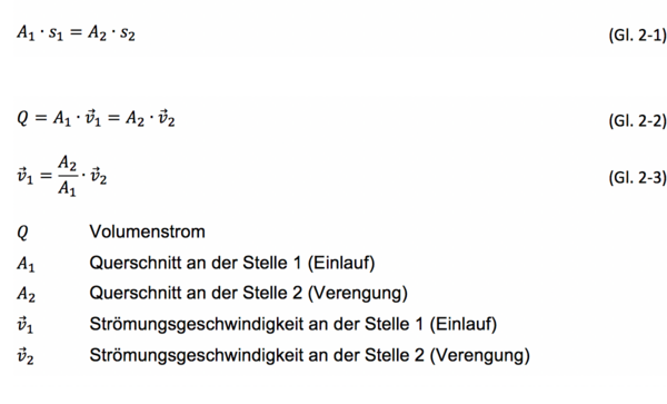
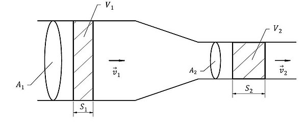
The differential pressure method is based on a throttle within closed pipelines with a full flow. By narrowing the cross-section at one point in the pipe, the flow velocity of the flowing medium is increased at the same volume flow. An ideal flow, in which the fluid is assumed to be frictionless, is described by the continuity equation (GL. 2-1).
Fig. 2-7 shows a graphical representation of the differential pressure method. Assuming an incompressible medium, the volumes V1= A1∙s1 and V2= A2∙s2 at points 1 (inlet) and 2 (constriction) are equal.
Using Bernoulli's equation, which is based on the assumption of a stationary process with an incompressible fluid, the flow velocities upstream or in the constriction can be calculated using the differential pressure ∆p = p2 - p1.
The equations do not take into account the losses caused by pipe friction and the resulting detachment of the jet. The jet can therefore no longer fill the entire cross-section of the throttle device. At the narrowest point, the cross-section is smaller than specified by the shape. In the standard, this is described by the flow coefficient α, which is determined empirically. For standardized throttle devices with incompressible fluids, the flow coefficient α depends only on the Reynolds (Re) number.
Orifices
The different types of orifice plates all have the same shape. They are differentiated according to DIN EN ISO 5167-2 by the position of the pressure tapping. The inner diameter of the orifice plate must always be greater than or equal to 12.5 mm. In addition, a diameter ratio of β = d/D ≥ 0.10 and ≤ 0.75 is specified. [DIN EN ISO 5167-2]
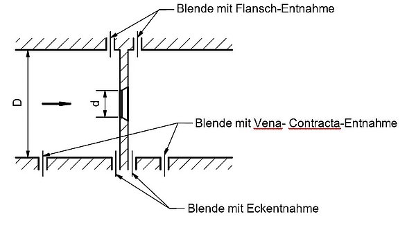
The pressure taps are realized either via individual holes or ring taps. The tapping points are divided into plus and minus pressure tapping points, which are located in front of and behind the orifice plate. The holes in the tapping points must all have the same diameter. They should also be burr-free and sharp. The diameter of the pressure tapping holes should be as small as possible and not exceed a maximum of 12 mm.
In general, the installation sizes including the measuring set-up of orifices are relatively large. This is due to the arrangement of the tapping holes and the resulting long mounting tubes. The corner orifice plate is an exception. The entire measuring arrangement can be realized as a single component due to the short mounting tubes. The measuring assembly therefore only needs to be placed between the flanges of the connecting pipe.
The flow pattern in the orifice plate is characterized by the sharp inlet edge. The flow breaks away from the wall and forms freely. Behind the edge, the jet constricts.
Nozzles
The standard deals with two types of standard nozzles and the Venturi nozzle. The standard nozzles can be further subdivided into the long radius nozzle and the ISA 1932 nozzle. (see Fig. 2-9) [DIN EN ISO 5167-3]
In contrast to the orifice, the flow inside the nozzle is forced through a rounded inlet and guided into a cylindrical duct with the same cross-section as the inlet. As a result, the jet exits without contraction.
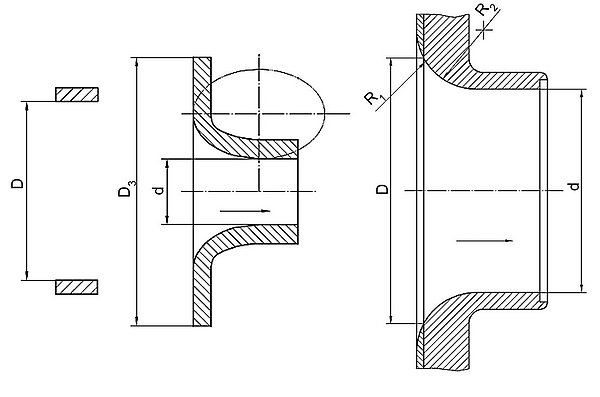
The ISA 1932 nozzles (also known as German standard nozzles) have almost constant flow rates for ReD > 105 due to the sharp rounding, while the flow rates of the long radius nozzle increase continuously with the Re number. However, the ISA 1932 nozzle is unusable below ReD = 105, as the jet breaks away from the nozzle wall in this range, leading to an erratic behavior of the flow rate α.
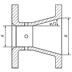
The Venturi nozzle is very similar in design to the standard orifice (see Fig. 2-12). The end face is identical to that of an ISA nozzle, but the cross-sectional constriction is returned to the original cross-section via a diffuser. The angle of the diffuser must be less than or equal to 30°. The diffuser contributes significantly to the pressure loss of the nozzle.
Venturi tube
Venturi tubes consist of conical and straight pipe sections, which have a pressure loss that is four to six times lower than that of orifices and nozzles. The DIN EN ISO 5167-4 standard defines three different types of classic Venturi tubes with
- cast-rough inlet cone
- machined inlet cone
- rough inlet cone welded from sheet steel
are distinguished.

The shape and position of the pressure tapping points are specified for each of the three versions. An opening angle of 21° ± 1° is specified for the inlet cone. The diffuser may have a total opening angle between 7° and 15° (see Fig. 2-11), but it is recommended to select a diffuser total opening angle between 7° and 8°, as otherwise flow separation will occur [DIN EN ISO 5167-4]. The classic Venturi tube may be shortened. It should be noted that the diffuser section may be shortened by up to 35 % of its length at the end. Within this range, there is no significant change in the pressure loss.
Products relevant to this article:
GRX-Q
![[Translate to Englisch:] Grindaix GRX-Q Volume flow sensor](https://grindaix.de/fileadmin/Public/Bilder/Products/10_GRX-Q/Grindaix_Volumenstromsensor_klein.jpg)
You may also be interested in these articles from our magazine:
Cooling during grinding
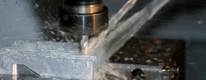
A great deal of heat is generated during grinding due to process-related friction. This heat must be reliably dissipated, which is why grinding processes require reliable cooling. You can read about what is important here.
GRX-Q - Volumetric measuring method
The volumetric measuring method is based on the measurement of partial quantities of a medium to be measured. The medium flowing through a defined measuring chamber or via an analog rotation of measuring vanes is added up.
GRX-Q - Displacement meter
With the displacement meters, the moving measuring walls are driven by the medium to be measured. The movement is recorded and counted.
GRX-Q - Flowed bodies
In this type of flow measurement, flow is applied to floating bodies, spring disks or flaps. After the differential pressure method, variable area flow measurement is one of the most frequently used methods.
