GRX-Q - Flowed bodies
In this type of flow measurement, flow is applied to floating bodies, spring disks or flaps. After the differential pressure method, variable area flow measurement is one of the most frequently used methods. In the following, the variable area flow meters as well as the spring disk and flap flow measurement are discussed in more detail.
Variable area flow meter
This method is used to measure the flow of liquids and gases. After the differential pressure method, the flow meter is one of the most frequently used methods and is characterized by a good price-performance ratio. It is easy to install and is very robust.
The flow measurement is realized with the aid of a resistance body in a conical measuring tube or a conical resistance body in an orifice plate. The measuring principle is based on a fluid flowing vertically from bottom to top around the resistance body. Under constant conditions, an equilibrium of forces is created between the fluid and the flow around the resistor body (see Fig. 2-12 - free-cut system).
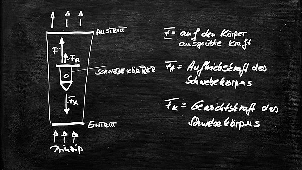
The change in the flow velocity of the fluid results in a change in height (lift height h) of the float, which is triggered by the dependence of the force exerted by the fluid. The relationship between the force and the flow velocity is based on the law of resistance.

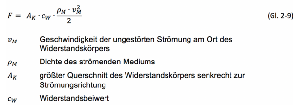
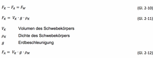
The weight and buoyancy of the floating body remain constant. The drag coefficient changes due to the conical tube with the height of the body and the Re number. The resulting equilibrium equation can be described as follows:
from which the equilibrium condition is:


In a measurement setup, the variables VK, ρK, ρM, g and AK are constant. This means that a change in the flow velocity vM only changes the drag coefficient cW. Thus, the relationship between the lift height h and the flow velocity vM is included in the drag coefficient cW. This means that the drag coefficient is a function of h and the Re number.
This means that it is not possible to calculate the drag coefficient. The values must be determined empirically by calibrating the measuring arrangement. This determination can be carried out with the help of VDI/VDE 3513. The guideline helps the user to create a flow scale in conjunction with the characteristic values of the fluid and the measuring device. The guideline can also be used to transfer an existing scale for the flow to a different medium.
The variable area flowmeters can be used with almost any gaseous or liquid medium. These measuring devices, which have a glass cone with the scale printed on it for direct reading, are very widely used. For opaque gases or liquids, variable area flowmeters made entirely of metal are suitable.
This measuring method is insensitive to dirt and contamination, provided that the particle size of the contamination does not exceed the width of the annular gap between the float and the conical measuring tube. Variable area flowmeters do not require a straight inlet section and can be used directly downstream of pipe bends or valves. The pressure losses of the devices are low and can be kept at a very low level with appropriate dimensioning. The accuracy of the sensors is specified as 2%, but it can be reduced to as little as 1% after extensive calibration.
Spring disc flowmeter
Spring disc flow meters work on a similar principle to that of the rotameter. Instead of the weight of the resistance body, the counterforce of a measuring spring creates a balance with the flowing fluid. [BON-02]
The measuring spring is rigidly connected on one side to the inlet of the conical measuring tube and on the other side to a freely movable spring disc (see Fig. 2-13). The spring is dimensioned so that even at maximum deflection, it remains well below the elastic limit. This ensures a long service life for the spring. The measuring spring with the spring washer are concentrically guided on a rod inside the conical measuring tube, on which they can be moved almost without friction.
The spring is deflected by the change in the flow velocity of the surrounding fluid until a state of equilibrium is restored. This means that the position of the spring disc is the measure for the respective flow.
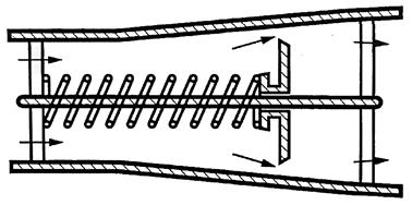
The following physical principles are based on a dynamic equilibrium between the flow and the spring force:
The volume flow qv is calculated from the mean flow velocity vM and the cross-section of the annular gap AR
Using equations (Eq. 2-15) and (Eq. 2-16)
the volume flow qv is obtained after equating and solving.
The range of application and possible uses of the spring disc flow meter are the same as those of the rotameter. The device is particularly characterized by the simple exchange of the measuring spring with scale. This allows the measuring range to be adapted to the respective conditions. As with the rotameter method, the flow meter is implemented in the pipeline and does not require any kind of flow section. Another advantage is the relatively small moving masses, which favor the dynamic properties of the system. A major difference compared to the variable area flowmeters is the independent mounting position. Due to the range spring used, the spring disc flowmeter can also be used in horizontal pipes.
Products relevant to this article:
You may also be interested in these articles from our magazine:
Types of cooling lubricants
In addition to emulsions of different concentrations, in which various additives are used, the use of grinding oils is also common. We have compiled the areas of application, advantages and disadvantages, as well as the most important selection criteria for cooling lubricants for you.
GRX-Q - Differential pressure method
Flow measurement using the differential pressure method is frequently used in chemical engineering and similar industries.
GRX-Q - Ultrasonic flow measurement
Ultrasonic flow measurement, also known as the transmission principle, works on the basis of the propagation speed of sound waves, which changes in moving liquids with the flow speed of the transmission medium.
GRX-Q - Magnetic-inductive flow measurement
In magnetic-inductive flow measurement (MID), an electrical voltage is generated by the interaction between the flow velocity of a liquid and a magnetic field. This principle is based on Faraday's law of induction.


