GRX-Q - Ultrasonic flow measurement
Ultrasonic flow measurement, also known as the through-sound principle, works on the basis of the speed of propagation of sound waves, which changes in moving liquids with the flow speed of the transmission medium (see Figure 2-15).
In this process, ultrasonic signals are sent back and forth alternately via the measuring probes attached to the outside of the pipe. In the case of stationary media, the signal propagates at the speed of sound c from A to B. If the liquid flows at a speed v in the same direction as the signal, the resulting speed is v+c. This means that the signal reaches probe B earlier than in stationary media. This principle also works in reverse under the same conditions. The resulting speed is v-c. This means that the signal propagates more slowly than in a stationary medium.
From this, it can be deduced that the time differences of these durations are a measure of the speed v of the medium.
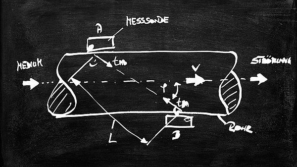
To determine the mean velocity, the signal is transmitted into the moving medium at an angle φ from point A to B (see Figure 2-15). The resulting sound velocity can be calculated from this using Equation 2-24.
The time tAB taken for the sound to travel from point A to B is calculated using the equation Eq. 2 - 25:
When sending in the opposite direction from probe B to A, the following applies: Eq. 26/27
By equating and subtracting (Eq. 2-24) and (Eq. 2-26), and inserting (Eq. 2-25) and (Eq. 2-27), the fluid velocity v can be determined as follows:
By measuring the sound propagation times tAB, tBA, the velocity v of the medium and thus the volume flow can be determined.
For c≫v, it is sufficient to measure the transit time difference ∆t=tAB-tBA. In this case, the following approximation applies:
A “pure” medium is a requirement for using the through-sound principle. There must be no suspended particles in the fluid. It should also be noted that the transit time difference ∆t is dependent on the material and temperature.
vortex flowmeter
This measurement method works according to the principle of Karman's vortex street. In this process, a baffle (vortex generator) is positioned perpendicular to the flowing fluid. Behind the body, vortices form at equal distances and in alternating directions. A stable “road” can be ensured by the ratio of the width of the road a to the distance L of 0.2806 (aL=0.2806).
The detachment of the vortices in the vortex body generates a flexural vibration f (frequency of the vortices per second). This flexural vibration is a measure of the flow velocity v. A key figure for determining the flexural vibration is the Strouhal number (Eq. 2-30).
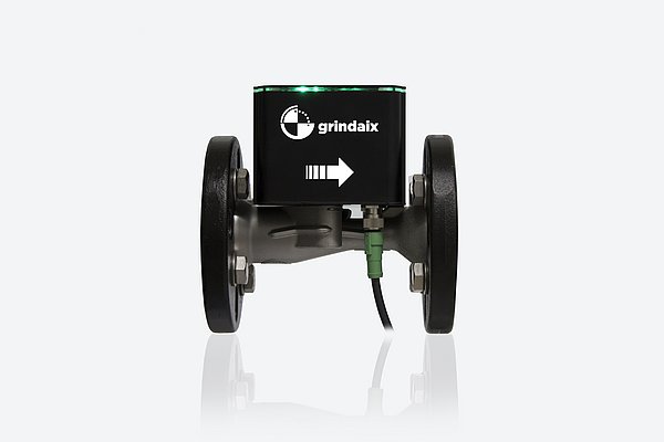

From (Eq. 2-32, it can be seen that the time intervals t are inversely proportional to the flow velocity v and proportional to the width b.
The flow rate is calculated as follows:
This method is used primarily for gases, vapors and low-viscosity or non-conductive fluids. The accuracy of the vortex flow meter is approximately 1% of the measured value.
Vortex flowmeters are low-maintenance because they have no moving parts. However, they are not suitable for small flow rates and require a long inlet and outlet section. In addition, the measuring range is limited by the Re number and viscosity.
[Translate to Englisch:] In diesem Artikel relevante Produkte:
GRX-Q
You may also be interested in these articles from our magazine:
Coolant filtration systems
Treatment is a crucial part of the cooling lubricant supply with a major impact on production results and efficiency. We have described and compared the usual filtration processes for cooling lubricants.
GRX-Q - Flow measurement
The flow measurement is part of the metrological determination of a volume flow Q or mass flow m=ρ∙Q. This is done as a function of a measuring cross-section A of a closed pipe or an open channel.
GRX-Q - Volumetric measuring method
The volumetric measuring method is based on the measurement of partial quantities of a medium to be measured. The medium flowing through a defined measuring chamber or via an analog rotation of measuring vanes is added up.
GRX-Q - Magnetic-inductive flow measurement
In magnetic-inductive flow measurement (MID), an electrical voltage is generated by the interaction between the flow velocity of a liquid and a magnetic field. This principle is based on Faraday's law of induction.


