Filtration system designs
On the market for coolant filtration systems, the user will find a wide range of technical implementations of the filtration principles described in the magazine article Filtration in the Coolant Cycle. The purpose of this chapter is to provide the user with an initial basic overview.
Filtration by magnetic force
Filtration by the action of magnetic force primarily refers to so-called magnetic separators. Magnetic separators are based on the principle of filtration by magnetic force. In magnetic separators, the coolant is guided along a surface that builds up a magnetic force field under the effect of a permanent magnet or electromagnet. In the first instance, magnetic filters therefore only filter magnetic dirt particles from the coolant. However, when magnetised dirt particles adhere to the surface, a filter cake is formed that can also separate non-magnetic dirt particles. Magnetic separators are available in a wide variety of designs. The following shows and explains the most common designs in practice.

Roller separator
The roller separator is the most common type of magnetic separator. It consists of a roller that rotates against the direction of flow of the coolant to be cleaned. When flowing over the magnetic roller, the coolant is freed from the dirt particles to be separated. The cleaning of the roller is usually done by a scraper integrated in the roller separator, which travels along the roller surface.
Cartridge separator
Cartridge separators, also known as magnetic cartridges, are mainly used to support cartridge filters (filtration by size differences). Magnetic cartridges are generally cylindrical filter elements that are inserted into filter streams and separate dirt particles on their surface by means of a magnetic field. Cleaning of magnetic cartridges is usually done by hand after removal.
Rod separator
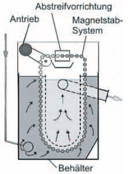
Rod separators essentially consist of several magnetic rods that are guided through the contaminated coolant with a slowly circulating chain. In the process, mainly the ferritic metal particles stick to the rods. The cleaning of the rods and the discharge of the dirt is done by an integrated scraper. Figure 1.1 shows a schematic diagram of such a separator. [VDI 3397]
Filtration through size differences
Filtration by size differences, also called sieve filtration, is technically implemented in different ways in the field of coolant filtration. This ranges from belt filters to drum filters to cartridge filters. Most system types can also be operated with precoat technology and backwash technology. Filtration by size differences is driven by gravity, negative pressure or pressure.
Band filter
Belt filters filter the coolant with the help of a sieve-like belt that is guided between deflection rollers. A schematic representation of a belt filter is shown in Figure 1.2. During filtration, the coolant flows through the filter belt and is freed from dirt particles. The separated dirt particles remain on the belt and form the so-called filter cake. The filter cake supports the filtration process by retaining finer particles than the pure belt. As the filter cake increases, the coolant flow rate decreases. Therefore, when a selected liquid level or differential pressure is reached, the belt is advanced and the dirt cake is scraped off the belt. At the same time, the filtration surface is provided with new belt and the filtration cycle can start again with clean filter media. Belt filters are equipped with filter consumables such as filter fleeces or with endless fabric belts.
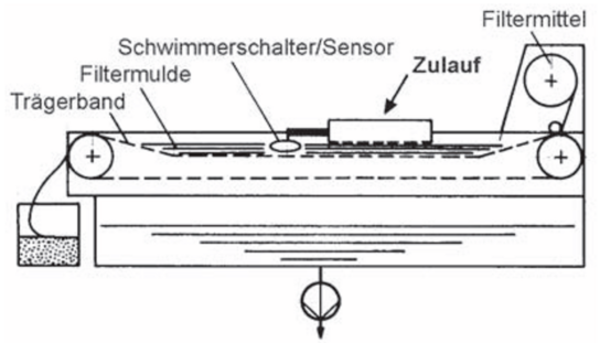
If filter fleece is used, it is guided over a carrier belt and wound up with an automatic device. If a continuous woven belt is used, the belt is cleaned after the filter cake is thrown off and used again for filtration. In practice, a brushing or backwashing device is often used for cleaning. The driving force in belt filters is given by gravity, negative pressure or positive pressure.
Drum filter
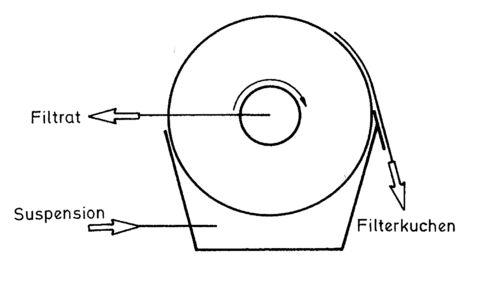
Drum filters filter the coolant with the help of a sieve-like drum. A schematic representation of a drum filter is shown in figure 1.3. The contaminated coolant flows onto the sieve-like surface of the drum for filtration. This separates the dirt particles and allows the cleaned coolant to flow into the inside of the drum and finally back into the coolant circuit. As with the belt filter, a dirt cake forms on the drum surface. This supports the filtration, but must be thrown off regularly due to the decrease in flow. For this purpose, the drum rotates along a brushing device when a defined liquid level or a defined pressure difference is reached. The filtration process can then be continued with a cleaned drum and optimum flow.
Cartridge filter
Cartridge filters generally consist of at least one filter dome and several filter elements contained therein, the filter cartridges. The filter cartridges are screwed into the filter dome and the coolant flows through them for coolant filtration. A flow from the outside to the inside is common. A filter dome with filter cartridges is shown schematically in Figure 1.4. During the filtration process, the dirt particles of the cooling lubricant are deposited on the surface of the filter cartridges. When a certain level of contamination is reached, the cartridges are removed and replaced by new ones (disposable cartridges) or cleaned by backwashing (reusable cartridges). There is a wide range of different designs and materials for filter cartridges.
![Grindaix_Figure 1.4: Cartridge filter [Gas00] Grindaix_Figure 1.4: Cartridge filter [Gas00]](https://grindaix.de/fileadmin/_processed_/3/b/csm_Grindaix_Kerzenfilter_Abbildung-1.4_baea2c3015.png)
Precoat technique
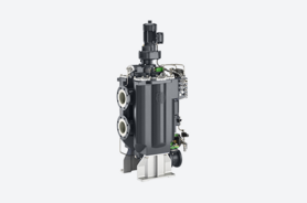
The precoating technique is characterised by the use of precoating agents. Precoating agents are filter aids (e.g. cellulose, diatomaceous earth, perlite) that adhere to the filter themselves and thus build up a filter cake that enables the filtration of finer particle sizes. Belt filters, drum filters, cartridge filters and other screen filters can be operated with the precoat technique.
References
[VDI 3397]: Richtlinie VDI 3397, Pflege von Kühlschmierstoffen für die Metallbe- und –verarbeitung, 2005
[Gas00]: Gasper, H.; Oechsle, D.; et al.: Handbuch der indust-riellen Fest/Flüssig-Filtration, 2. Auflage, Weinheim, Wiley-VCH, 2000
You may also be interested in these articles from our magazine:
Zero Emission Production

Zero Emission Production helps to sustainably reduce carbon dioxide emissions while increasing the availability of production equipment and avoiding the waste of operating materials.
GRX-Q - Magnetic-inductive flow measurement
In magnetic-inductive flow measurement (MID), an electrical voltage is generated by the interaction between the flow velocity of a liquid and a magnetic field. This principle is based on Faraday's law of induction.
