Technical possibilities for influencing air cushions
Various methods commonly used in practice are applied to overcome the air cushion. The aim in all cases is to minimize or completely avoid the negative influence of the air cushion on the cooling lubricant jet. The available options for overcoming this depend on the nozzle design used. In principle, the following technical options can be identified:
1. penetration of the air cushion with the coolant jet, by adjusting the nozzle parameters (volume flow, pressure, jet angle)
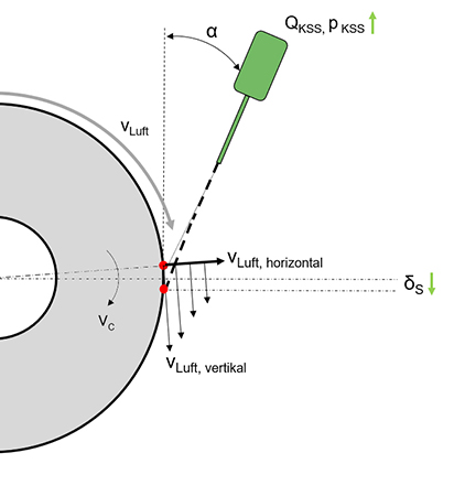
This approach is particularly suitable for free-jet nozzles. By adjusting the coolant exit speed or the positioning angle, it can initially be achieved that the point of impact of the coolant jet is above the cutting point despite the jet deflection. The point of impact is brought forward by the amount of the deflection, so that it then meets the requirement in the influenced state. Furthermore, there is an increase in the horizontal flow force component of the cooling lubricant jet, which means that the jet can supply the cutting point with cooling lubricant despite the influence.
As shown in Figure 1, adjusting the coolant parameters for free-jet nozzles can prevent the coolant from missing the cutting point, thus improving the coolant supply. With regard to the relevance of the cooling lubricant exit speed from the cooling lubricant nozzle, Heymann cites not only the development of the jet force but also the necessity of accelerating the jet to the peripheral speed of the grinding wheel [3]. The exit speed is identified by Beck as an influencing factor on the kinetic energy of the cooling lubricant jet and as an important cooling lubricant parameter to ensure penetration of the air cushion. However, economic disadvantages due to the resulting increase in cooling lubricant volume flow must also be taken into account [4].
2. Deflecting the air cushion with mechanical barriers
A common solution is to weaken or deflect the air cushion using fixed barriers. Air baffles are typically used for this purpose, which are designed to deflect the air cushion in front of the point of impact of the cooling lubricant jet. Yoshimi et al. carried out CFD simulations and experiments to determine the flow conditions within the air cushion when air baffles are used. Figure 2 shows the effect of an air baffle based on a CFD simulation.
![Figure2: CFD-Simulation – air cushion with deflector plate [5] Air cushion with deflector plate [5]](https://grindaix.de/fileadmin/_processed_/0/5/csm_Grindaix_GmbH_Ableitblech_Abbildung-2_738e181e05.jpg)
The reduction in the thickness of the air cushion layer directly behind the air deflector plate is clearly visible. The flow velocities, in particular those of the fast boundary layer at the grinding wheel, are momentarily no longer present directly behind the deflector plate. However, it should be noted that the influence of the air deflector plate can only be maintained over a very limited area of the grinding wheel. Just 90° in the direction of rotation of the wheel, the boundary layer near the surface almost reaches its original speed again. For an optimal combination of the air baffle with a cooling lubricant nozzle, the nozzle would have to be arranged directly behind the baffle so that the cooling lubricant jet can hit the weakened area of the air cushion. The disadvantage of this solution is the very high setup effort involved, as well as the need for readjustment of the barrier when the grinding wheel wears [4]. When high-speed grinding with free-jet nozzles, the benefit of deflector plates is generally considered to be high. [1].
However, when using an air deflector plate, it should be noted that if the grinding wheel rim wears radially, the gap to the air deflector plate increases. If the air deflector plate is then not readjusted at discrete times, an increasing gap will develop between the grinding rim and the air deflector plate. This gap exacerbates the formation of an air cushion rotating with the grinding wheel in such a way that the air cushion in relation to its speed profile compared to the undeflected air cushion even increases. The plate then acts like a “diaphragm” and worsens the situation significantly under certain circumstances.
When developing their nozzle solutions, the nozzle experts at team grindaix always ensure that an air cushion is weakened and deflected effectively over the entire radius of the grinding tool.
3. Using chamber or shoe nozzles
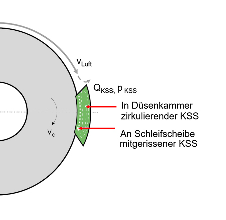
Another option for deflecting the air cushion with fixed, mechanical barriers and simultaneous combination with the cooling lubricant supply is the so-called shoe or chamber nozzles. With this nozzle design, a certain segment of the grinding wheel surface is covered by the chamber nozzle. This chamber is filled with cooling lubricant, which is carried along by the grinding wheel due to its rotation and accelerated to the circumferential speed.
Due to the housing of the chamber nozzle and its very close fit to the grinding wheel, the air cushion is completely deflected in front of the coolant supply point. This means that the grinding wheel can be wetted with coolant without being affected by the air cushion.
The disadvantage of this solution is the necessity of a tight fit of the chamber nozzle to the grinding wheel surface. This is associated with a high level of setup and adjustment effort. However, the adjustment of the discharge element and the cooling lubricant supply is carried out in a single operation, which can further reduce the labor required compared to a combination solution consisting of a discharge sheet and cooling lubricant nozzle [2], [4].
However, the use of chamber nozzles is rather unsuitable for complex grinding wheel geometries or for grinding wheels with a high wear-related diameter reduction [1]. It should also be noted that, due to the necessity of accelerating the cooling lubricant from the nozzle chamber, part of the spindle drive power must be applied, which can no longer be provided to the grinding process as a result.
4. Deflecting the air cushion with additional cooling lubricant nozzles
![Figure 4: Schematic representation of the function of two-jet nozzles according to H.W. Ott, cf. [2] Function of two-jet nozzles according to H.W. Ott, cf. [2]](https://grindaix.de/fileadmin/_processed_/2/0/csm_Grindaix_GmbH_Funktion_Zweistrahlduese_Abbildung_4_8fc2fa6f1f.jpg)
H.W. Ott introduces a coolant supply system that can be used not only to supply coolant into the grinding gap and to deflect the air cushion, but also for grinding wheel cleaning. This so-called two-stream nozzle divides the supplied coolant flow rate. The main part of the flow rate is directed to the grinding gap, as with conventional cooling nozzles, and used for process cooling.
The comparatively smaller part is directed through flat-spray nozzles at a 90° angle, directly onto the grinding wheel surface. This creates a barrier for the air cushion, which should make it easier for the coolant jet to reach the grinding wheel for process cooling.
As a positive side effect, good cleaning properties are also achieved by flushing machining residues out of the pore spaces of the grinding wheel, which additionally positively influences the machining result. The coolant volume flow used for cleaning is also almost completely available for process cooling due to entrainment in the grinding wheel pores. [2] Figure 3 shows the schematic functioning of the nozzle system according to H.W. Ott.
Potentials for effective penetration of the air cushion
The technical efforts described to reduce the influence of the air cushion on the cooling lubricant jet clearly demonstrate the relevance of these measures for production technology. This is primarily due to the fact that correct penetration of the air cushion can have a very positive effect on the productivity of the grinding process.
The priority is to ensure that the supply to the cutting point is reliably guaranteed in order to avoid thermal damage to the component and overloading of the tool. This basic requirement for the cooling lubricant supply can be significantly impaired by the air cushion. Effective penetration of the air cushion therefore increases the robustness of the machining task.
The economic efficiency of a machine tool depends on the reliable production of many components of perfect quality within a short machining time. The decisive factor here is the achievable cutting performance, which can only reach the required level with high infeeds or high cutting speeds. A sufficient cooling capacity to dissipate the heat energy generated is essential for this. The reliable lubricoolant supply to the cutting point, despite the presence of the air cushion, therefore offers the potential to significantly increase the cost-effectiveness and efficiency of a machine tool.
In addition to process cooling, reliable grinding wheel cleaning also has a major influence on the machining process. A clogging of the grinding wheel pores with chips shortens the dressing intervals, the transport of cooling lubricant in the pore spaces is impeded, the cutting performance decreases and the temperature development increases. As the jet from flat jet nozzles, which are usually used as cleaning nozzles, is also subject to the influences of the air cushion, an adequate strategic approach must also be found here to avoid jet deflection. In addition to eliminating the above-mentioned negative influences, reliable grinding wheel cleaning contributes to an improvement in the finishable surface quality.
Summary
In summary, the elimination of the disturbing influence of the air cushion on the cooling lubricant jet, regardless of the type of nozzle used, can be regarded as the primary challenge of production engineering in the field of grinding technology.
Do you need support from an expert in this field? Then do not hesitate to contact us. We will analyze your grinding process and offer you an individual solution.
Sources
[1] Denkena, Berend. Tönshoff, Hans Kurt. Spanen - Grundlagen, Heidelberg 2001.
[2] Meister, Markus. Vademecum des Schleifens, München 2011.
[3] Heymann, Tobias. Schleifen und Polierschleifen von wendelförmigen Spannuten von Vollhartmetallbohrwerkzeugen, Dortmund 2015.
[4] Beck, Thorsten. Berichte aus der Produktionstechnik, Kühlschmierstoffeinsatz beim Schleifen mit CBN, Aachen 2001.
[5] Yoshimi,T.; Oishi, S.; Okubo, S.; Morita, H. Development of Minimized Coolant Supply Technology in Grinding, JTEKT Engineering Journal English 2010.
Products relevant to this article:
You may also be interested in these articles from our magazine:
Cooling lubricant nozzles
Cooling lubricant nozzles generate the necessary outlet speed of the coolant. However, nozzles are not only required for cooling applications. You can find an overview of all applications and designs here.
Cooling lubricant and its relevance in grinding processes
Cooling lubricant is particularly relevant in the grinding process. But why grinding in particular? And what happens if the cooling lubricant is not used correctly? We answer these questions in this article.
