Flow analysis of the air cushion
Based on the phenomenon of boundary layer adhesion described in the magazine article, Interference with the cooling lubricant supply during grinding Air cushion, additional investigations into the shape and characteristics of the grinding wheel air cushion are available in the literature. In addition to FEM (finite element methods) and CFD (computational fluid dynamics) analyses, optical measurement methods using a laser Doppler anemometer are also used. To compare the shape of the air cushion with the cutting speed vc of the grinding wheel and to be able to relate them to each other, the flow velocity of the air cushion in m/s is to be regarded as a significant measured variable.
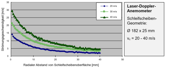
Figure 1 clearly shows the fast air layer near the surface of the grinding wheel. The decrease in speed with increasing radial distance from the grinding wheel can also be seen. According to Wu/Morgan, the decrease in flow speed in the air cushion is described as exponentially falling. The air speed measurement using a laser Doppler anemometer shows this relationship for various circumferential speeds vc between 20–40 m/s.
The measured values obtained can be used to characterize the velocity profile of the air cushion. The highest flow velocities of the air cushion are close to the surface of the grinding wheel. At a distance of 0 mm, these correspond analytically to the peripheral speed of the grinding wheel. At the measuring point of the smallest radial distance, there is already a significant decrease in flow velocity, which continues to fall quadratically with increasing distance.
Further informative findings were obtained in detailed investigations by Prof. Dr. Ing. Wilfried Saxler and Mr. M.Eng. Roman Stabauer at the Rheinische Fachhochschule der Stadt Köln (Cologne University of Applied Sciences) on the subject of air cushion characterization during grinding. To characterize the air cushion, the flow velocity and the dynamic pressure in the radial and axial directions of the grinding wheel were measured using a Prandtl tube.
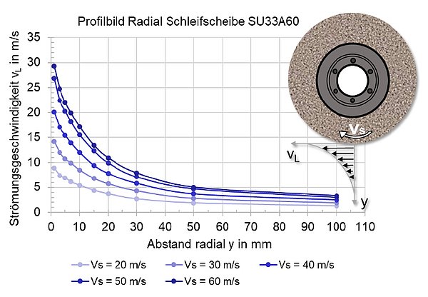
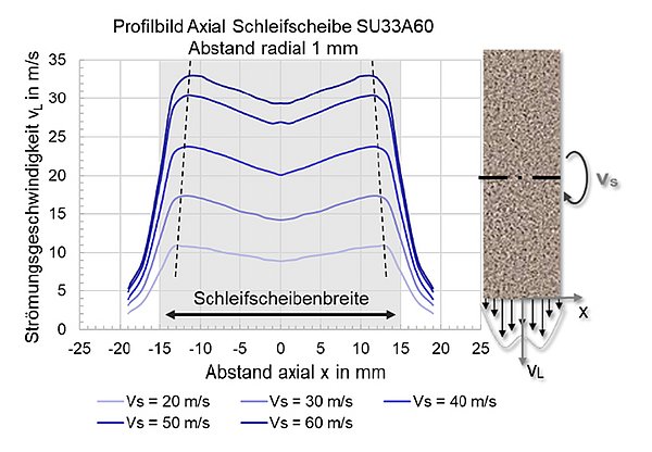
First, the flow velocity of the air cushion in the radial direction to the grinding wheel was examined. The measuring point of the Prandtl tube was positioned exactly in the center under the grinding wheel (open-pored corundum, grain size 60) and the flow velocity was measured at different distances in the radial direction (Figure 2). In addition, the flow velocity of the air cushion in the axial direction, i.e. across the width of the grinding wheel, was measured (Figure 6, right). In this case, the distance of the Prandtl tube was as close as possible to the grinding wheel. Furthermore, the cutting speed of the grinding wheel was varied between 20 and 60 m/s in both test series.
At a cutting speed of 20 m/s, the flow velocity at the first measuring point of 1 mm distance is approx. 9 m/s. With increasing radial distance, the flow velocity drops exponentially and is only just over 2 m/s at a distance of 50 mm. At a distance of 100 mm, the flow velocity is already so low that the measuring instrument can hardly detect any difference compared to a measurement without a rotating grinding wheel. The same behavior can be observed when the grinding wheel's peripheral speed is increased up to 60 m/s. It is striking, however, that the flow velocity of the air cushion just above the surface of the grinding wheel is less than 50% of the set grinding wheel peripheral speed. At 60 m/s, only about 30 m/s of flow velocity can be measured. When observing the measurements of the air cushion over the grinding wheel width, it can be seen that the air cushion does not build up evenly over the wheel width. The air cushion increases towards the edges of the grinding wheel and the higher the wheel peripheral speed, the more pronounced this effect is.
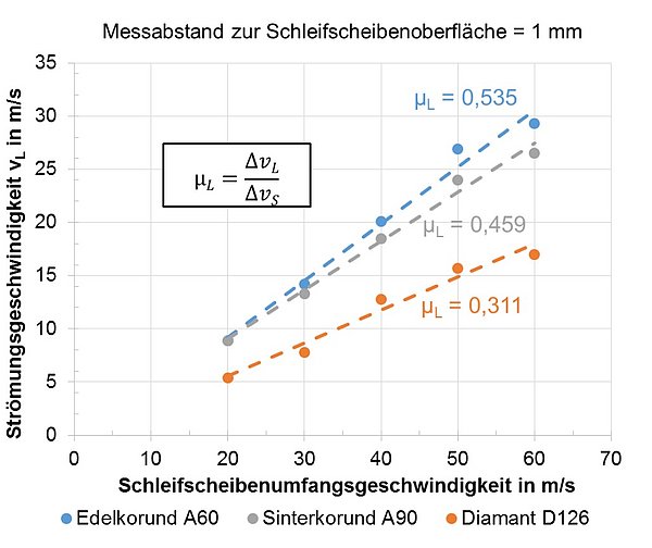
The same tests were also carried out with a finer and denser sintered corundum grinding wheel, a very fine and closed diamond wheel and a smooth steel wheel. It became clear that the flow velocity, and thus the influence of the air cushion, decreases with a finer grain and a smoother wheel surface. A coarse and porous grinding wheel can carry more air and accelerate it more. A diamond grinding wheel with a dense bond has no porosity and can be compared to a smooth steel wheel in terms of the air cushion. There is hardly any difference to be observed here, although the surface roughnesses differ significantly. Porosity thus has a greater influence than the topography of the surface.
If the grinding wheel peripheral speed and the associated flow speed of the air cushion of different grinding wheels are plotted in a diagram (Figure 4), an almost linear course can be observed. The curve for the open-pored and coarser white aluminum oxide grinding wheel has a steeper slope than the curve for the denser and finer sintered aluminum oxide grinding wheel. In comparison, the curve for the closed diamond grinding wheel with a very fine surface topography has a significantly flatter slope. A defined slope μL for various types of grinding wheels thus makes it possible to describe the formation of the air cushion at different wheel peripheral speeds. A series of experiments were carried out using a high-speed camera to analyze the interactions between the coolant supply and the air cushion. For example, it was observed how the coolant jet, which hits the wheel tangentially, behaves when the peripheral speed or the exit speed is increased.
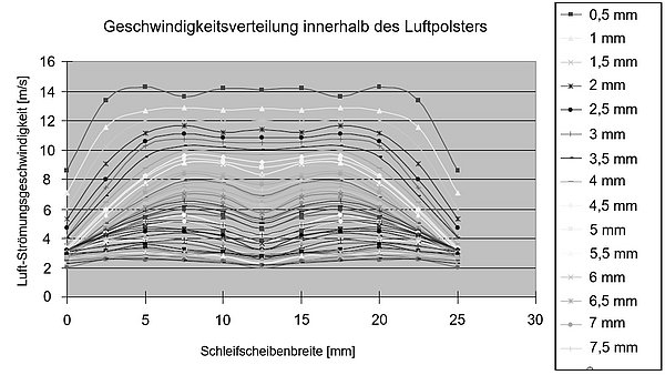
Wu and Morgan evaluated the change in the air cushion speed across the width of the grinding wheel in the axial direction using a speed profile in 2009 (see Figure 5). It was also recognized and mentioned that the air cushion flows at lower speeds on the flanks of the grinding wheel than in the center of the grinding wheel. Between the flanks, a stationary speed range can be observed as a function of the radial distance from the grinding wheel surface and the axial position. This finding from the investigation using a laser Doppler anemometer is in contradiction to other investigations, which report a maximum flow velocity in the center of the grinding wheel and two distinct velocity increases to the left and right of the center position [Wu/Morgan].
Summary
In summary, the grinding wheel air cushion can be reduced to a vertical and a horizontal flow force component with regard to the flow velocities that occur. These arise from the internal friction of the air and from boundary layer adhesion between the air and the grinding wheel. According to Wu/Morgan, these can be transferred into an x- and y-coordinate direction. By using optical measurement techniques (laser Doppler anemometer), the velocity profile of the air cushion can be determined. A quadratic falling gradient can be determined for the development of the velocity as a function of the radial distance. When the velocity profile is viewed axially, the flank areas of the grinding wheel show significantly lower flow velocities compared to the center.
Benefit from our knowledge
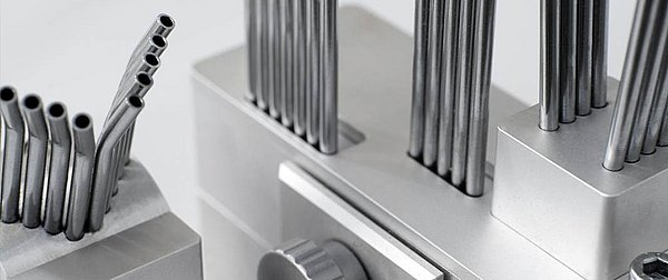
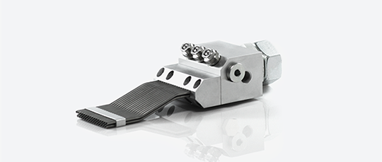
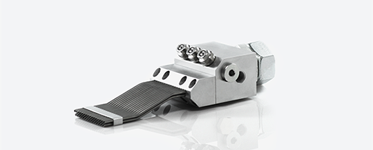
The team Grindaix offers its customers a professional design of nozzles that allow the air cushion to be weakened in line with requirements in such a way that it no longer has a negative influence on the cooling lubricant supply during grinding. These nozzles are offered by Grindaix under the technical designation GRX-LAS nozzles. When it comes to professional and expert nozzle engineering, the cooling lubricant supply experts at Grindaix always ensure that no unwanted aerosol formation occurs in the grinding machine's machine compartment. When oil is used as the cooling lubricant, this can lead to oil-air mixture explosions and, in the worst case, to machine fires. Excessive aerosol formation also leads to an increased discharge of cooling lubricant from the grinding machine via air extraction units or, in the case of non-encapsulated machines, simply into the machine hall via the ambient air. This leads to a negative impact on the working environment of the machine operators (risk of slipping/contamination of the ambient air, etc.).
Sources
Sax/Stab: Sachbericht des Projektpartners, Institut für Werkzeug- und Fertigungstechnik der RFH Köln mit dem AiF Förderkennzeichen ZF4420502RF7; Prof. Dr.-Ing. Wilfried Saxler, M.Sc. Roman Stabbauer – Textpassagen wurden teilweise vollständig übernommen.
WU/Morgan: H. Wu, M. N. Morgan, B. Lin. Investigation of the Grinding Wheel Air Boundary Layer Flow. Schweiz : Trans Tech Publications, 2009. 1662-8985.
Products relevant to this article:
You may also be interested in these articles from our magazine:
Options for influencing the air cushion
Various standard practical solutions are used to overcome the air cushion. The aim in all cases is to mitigate or completely avoid the negative influence of the air cushion on the cooling lubricant jet.
Cooling lubricant nozzles
Cooling lubricant nozzles generate the necessary outlet speed of the coolant. However, nozzles are not only required for cooling applications. You can find an overview of all applications and designs here.
