Pressure control systems for cooling lubricants
In most cases, production lines in the metalworking industry require cooling lubricants to ensure that components are processed in a qualitatively flawless, economical and thermally undamaged manner. The two main tasks of the cooling lubricant are cooling (dissipating heat energy) and lubricating (reducing friction between the workpiece and the tool). However, the cooling lubricant can also perform additional tasks in the process (e.g. chip transport). Oils and emulsions (water-in-oil mixtures) are mainly used. The coolant pressure plays an important role here, because it is directly related to the coolant volume flow (consumption) of a production unit. On the basis of a coolant system analysis (e.g. using a coolant audit), the machine operator can determine the exact supply conditions within his machine tool, in particular when, how much coolant and, in the best case, how much coolant is needed at which point and at which time for his current machining process.
The previously propagated productivity farce “The more, the better!” is no longer the measure of all things. Rather, the most productive companies are differentiating themselves through a more targeted and application-optimized cooling lubricant management.
The coolant pressure supply in manufacturing plants plays an important role in this. On the one hand, it centrally supplies the machines connected to the cooling lubricant system with sufficient cooling lubricant. On the other hand, it regulates the cooling lubricant supply decentrally within a single machine tool on a cycle-by-cycle basis. For example, higher cooling lubricant pressures are often used at the supply point to cool the machining process during the roughing cycle than is the case in the fine finishing cycle. In addition to ensuring optimum cooling and lubrication of the machining process for maximum productivity requirements, an exact pressure supply also offers the tools a maximum service life with an optimum cooling lubricant supply. Reject rates (thermally damaged components due to grinding burn) are significantly reduced. If, at the same time, the amount of cooling lubricant used can be kept low, thus reducing cooling lubricant operating costs, and the required cooling lubricant filtration quality can be met, then a significant comparative competitive advantage arises from the application of a suitable cooling lubricant monitoring system.
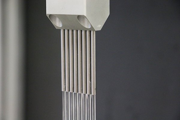
Pressurized supply of a machine tool
The manufacturing process is divided into different cycles. The rough pre-machining with high infeeds and equally high material removal rates is called a roughing cycle. The component surfaces achieved are often less relevant. The focus here is on maximizing the productive shaping of the component in the shortest possible time. In contrast, the focus during finishing and fine finishing is on the surface quality of the machining point and compliance with the dimensional, shape and position tolerances. In the roughing cycle, higher cooling lubricant pressures and correspondingly higher cooling lubricant quantities are often required than in finishing, since the process energy introduced here can be significantly higher than in finishing. During the finishing process, the formation of an “aqua planing effect” is also avoided, which can lead to improper floating between the component and the tool. This effect causes a negative impact on the tolerances for form, dimension and position.
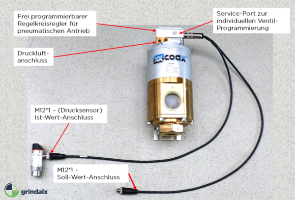
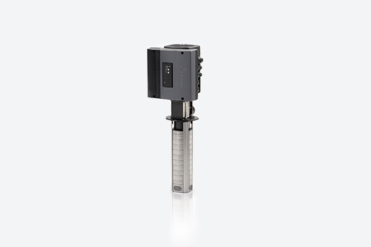
To adjust the cooling lubricant supply parameters, the machine control system transmits pressure setpoint values either to a frequency-controlled pump or to a pressure control valve. The aim here is to provide the pressure as accurately as possible and at the same time with rapid variations in response times <300ms without pressure surges in the cooling lubricant line system of the machine.
If a cycle-related cooling lubricant supply with all its economic advantages cannot be used on the machine tools because they do not have a pressure control valve and only have stationary cooling lubricant pumps, i.e. pumps without frequency control of the pump speed, there are basically two different options.
You can choose between
- a retrofit of the stationary pump with a frequency converter for a frequency-controlled pressure adjustment,
or
- using a pressure control valve.
Both variants are common in practice and are compared within a coolant system analysis (coolant audit) in terms of their economic efficiency and the risk of a technically clean implementation.
When a pressure control valve is used, the setpoint value from the control system (HMI) of a machine tool is sent directly to a pressure control valve. The lubricoolant valve is adapted and calibrated to the respective application during installation. To do this, the control and action times, pressure curves during pressure adjustment processes and the avoidance of pressure surges in the lubricoolant line system are set according to requirements.
Central pressure control for the supply of production lines
In conventional cooling lubricant central supply systems, there is a pressure station located near the central cooling lubricant filtration system. Depending on the wear condition and the quantity taken off by the cooling lubricant consumers (machine tools), these maintain a constant cooling lubricant pressure in the cooling lubricant feed line systems.
However, since the amount of coolant removed by the individual coolant consumers (machine tools) varies greatly, as the machines require different amounts of coolant at different times, the supply situation within these coolant supply systems is uneven. In the worst case, this can lead to machines that are set up close to the central pressure supply unit receiving too much coolant and machines that are further away receiving too little coolant. The machine operators then regulate the coolant supply using manual ball valves at the machine inlet. Over time, this results in very irregular coolant supply and undersupply scenarios, which can have a significant negative impact on the productivity of the individual machine tools and their work results. As a result, the robustness of the manufacturing units decreases and the improper manual control effort increases. The system is thus unstable in terms of coolant supply.
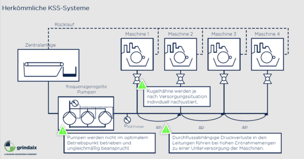
In the case of widely varying demand scenarios, the pumps of the cooling lubricant pressure supply station are not operated at their optimum operating point, which can lead to high power consumption and an increase in mechanical wear on the pumps. Furthermore, the pressure losses in the pipelines increase with an increase in the total cooling lubricant volume flow due to higher pipeline flow velocities.
In order to prevent such strong pressure and resulting coolant volume flow fluctuations, a so-called coolant constant pressure control is used in most cases. In this case, a central pressure supply unit feeds coolant into the coolant supply systems until a predetermined target pressure value is reached.
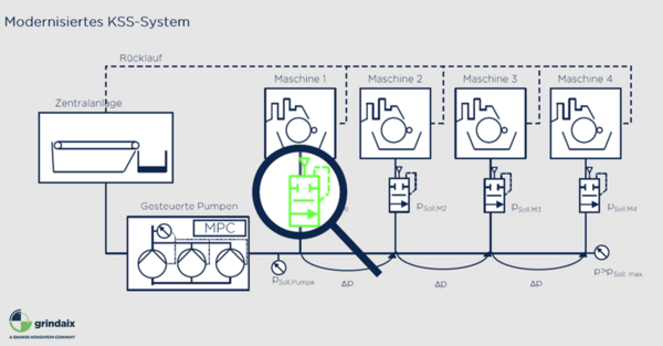
This pressure value is measured at the point in the cooling lubricant supply system that is furthest from the pressure supply unit. This type of pressure control is sometimes also referred to as “bad point control”. To enable the machine tools to obtain a constant coolant pressure from the coolant supply system, pressure control valves are installed in front of the machines. These are individually adjustable and constantly supply the machine with only the set coolant pressure at all times, provided that the set coolant pressure is present in the coolant supply system. If the CL consumption rate varies, for example because several machines are operating simultaneously at maximum CL demand, the pressure in the CL supply system initially drops. This is diagnosed by the pressure sensor at the end of the CL supply line and the frequency control of the pressure supply station is adjusted to a constant pressure level. This happens so quickly that there is never an undersupply to a machine connected to the cooling lubricant supply system. An oversupply of cooling lubricant is prevented by the fact that the pressure control valves installed upstream of the machines limit the cooling lubricant supply in terms of the cooling lubricant volume flow. The following figure shows a schematic representation of this type of constant pressure control.
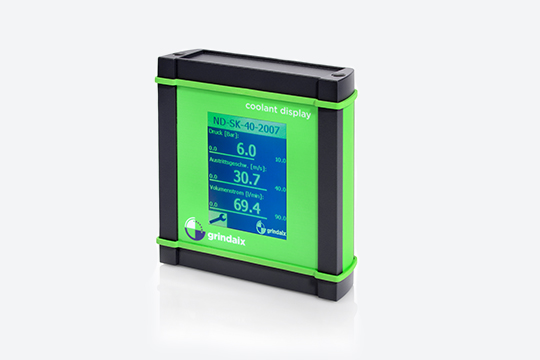
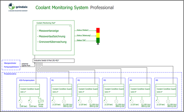
It is now interesting to ask when which machine consumes which quantity of coolant at what time. This information is now collected via coolant monitoring systems and can be traced back with sufficient accuracy at a sampling rate of 1 Hz, for example. The collected coolant data, such as pressure and volume flow at the respective machines, is continuously recorded, visualized and stored. This enables the user to identify exactly whether the cooling lubricant supply situation at a given time (3:45 a.m. in the night shift) can be considered as a cause of any component defects (complaints). Furthermore, if the cooling lubricant volume flow at the individual machine tools is diagnosed, predictions can be made regarding the full functionality of the pressure control valves. Since all pressure control valves are subject to high abrasive wear due to the unavoidable dirt deposits in cooling lubricants, the respective wear progress is documented by means of a pressure monitoring device before and after each pressure control valve, and after the data has been evaluated, this allows for predictive maintenance.
Summary
Modern cooling lubricant supply systems feature a constant pressure control for all cooling lubricant consumption points. They are monitored continuously so that both faulty cooling lubricant supplies can be diagnosed and failure scenarios of mechanical cooling lubricant system components can be predicted.
The team at grindaix will take care of your pressure supply needs in a professional manner. Contact us at info@grindaix.de
Products relevant to this article:
You may also be interested in these articles from our magazine:
Grinding technology
Our article “Grinding technology” provides an overview of the complex topic of grinding technology with its many influencing factors. Here we offer you a complete overview of all relevant parameters.
Frequent problems during grinding
Modern high-volume production facilities for metal components often have large and equally complex cooling lubricant systems. Keeping an eye on all parameters and ensuring reliable operation is therefore no trivial matter. Coolant monitoring systems can be used to support the monitoring of the cooling lubricant system.
Cleaning of cooling lubricant
Why does cooling lubricant need to be cleaned and what options are there for this? What needs to be considered and where is there potential for increasing efficiency? You can read this and other interesting facts about cooling lubricant cleaning here.
Coolant filtration systems
Treatment is a crucial part of the cooling lubricant supply with a major impact on production results and efficiency. We have described and compared the usual filtration processes for cooling lubricants.
