A concept for controlling the GRX-X multifunction nozzle
In the following we describe a concept how the GRX-X multifunction nozzle developed by the Grindaix team can be controlled and regulated in a practical way within a grinding machine with only a few components. With the controlled multifunction nozzle, the productivity limits of the grinding process can be extended with regard to thermal damage-free processing.
The multifunction nozzle consists of three individual nozzles (see figure 1). The cooling nozzle to cool the grinding wheel, the cleaning nozzle to clean the grinding wheel coating from clogging and abrasion and the GRX-LAS Liquid Air Spoiler. The Liquid Air Spoiler GRX-LAS diverts the air cushion, which is created by a fast rotating grinding wheel, away from the grinding wheel and thus improves the coolant supply to the contact point.
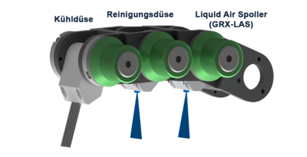
Figure 1: Grindaix GRX-X multifunction nozzle
All three nozzles are individually controlled via an HMI on the basis of a separate software solution and depending on the current grinding process. The operator enters the desired coolant supply parameters for each nozzle chamber to be operated separately and cycle-related in the user interface. Based on these parameters, the software independently controls and regulates the cooling lubricant supply of the respective nozzle elements in the grinding process.
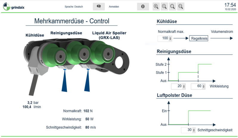
Figure 2: Grindaix tool for controlling the multifunction nozzle
In addition, the process data collected in connection with the multifunction nozzle are displayed and recorded. The recorded process data can then be exported or made available to other systems.
Control of the cooling nozzle (needle nozzle)
The aim is to ensure that the grinding tool-related normal force does not exceed a limit value (adjustable by the operator, see figure 3). The deciding factor here is the volume flow of the cooling lubricant at the cooling nozzle. At the cooling nozzle the volume flow is controlled by means of a pressure control valve. If the normal force exceeds the set granulation value, this is equivalent to the occurrence of an "aquaplaning effect" between the grinding tool and the component surface. In this case the volume flow at the needle nozzle is reduced by the control.

Figure 3: Cooling nozzle control
Control of the cleaning nozzle
The effective power of the grinding wheel drive is decisive for the cleaning nozzle as input signal and control variable. If the grinding wheel becomes clogged with increasing grinding time, the effective power of the motor spindle increases. If the active power exceeds a limit value, this is counteracted by switching on the cleaning nozzle. The pore spaces of the grinding wheel bond which are clogged with chips are flushed free, friction in the machining process is reduced and the effective power decreases. The cleaning nozzle can be switched on in two stages, for example (see figure 4).
If the effective power rises above the limit value set in the first stage, the first valve is opened and the cooling lubricant flows through the cleaning nozzle. If this is not sufficient and the effective power continues to increase, the second stage is additionally activated to increase the cleaning effect. The associated pressure supply of the cleaning nozzles is based on the specific nozzle characteristic curve of the Grindaix GmbH.
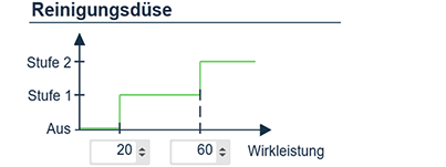
Figure 4: Two-level control of the cleaning nozzle
Control Liquid Air Spoiler GRX-LAS
The Liquid Air Spoiler is intended to break through the air cushion on the grinding wheel with the aid of a jet of cooling lubricant and to discharge it radially from the grinding wheel surface. The air cushion is only created above a certain speed when the grinding wheel is rotating. The speed of a grinding wheel is controlled by the required peripheral speed of the grinding wheel. Thus the decisive variable for controlling the Liquid Air Spoiler is the grinding wheel peripheral speed vs or the grinding spindle speed ns with known grinding wheel diameter dsi at time t=i.
The operator can select exactly the desired grinding wheel surface speed in a control software, from which point the nozzle is automatically switched on to discharge the air cushion (see figure 5).
With this nozzle, too, the desired volume flow is set by means of a valve. In the later course of the process, a characteristic curve of the air-cushion nozzle can be used to set the correct cooling lubricant quantity and the corresponding correct cooling lubricant pressure for an appropriate air-cushion drainage system. The speed of a frequency-controlled pump is controlled in the appropriate ratio to the pressure/flow rate.
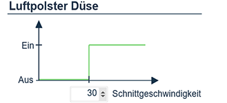
Figure 5: Control of the GRX-LAS Liquid Air Spoiler

Figure 6: Measured values of the multifunction nozzle
Display and recording of process parameters
In order to display the current process parameters to the operator, the nozzles are equipped with a sensor system that meets the requirements. The cooling nozzle is fitted with the high-precision GRX-Q, which simultaneously measures the coolant pressure, the coolant volume flow and the coolant temperature with virtually no wear.
In order to additionally display the outlet speeds of the cooling lubricant at the nozzles, the Grindaix nozzle characteristic curve is stored for each nozzle. This allows the software to calculate the exact outlet speed of the coolant in each chamber of the multi-function nozzle as a possible equivalent of the mode of operation.
The cleaning and air cushion nozzles each have their own pressure sensor in the inlet of the nozzle. This allows the most important system parameters to be recorded simultaneously. All measured values are then displayed in a user interface and simultaneously recorded (see figure 6).
The system structure
The following picture (see figure 7) shows an overview of the components, signals and their interaction of the concept.
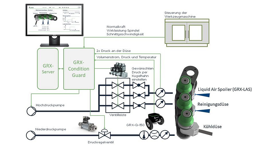
Figure 7: System components
The content presented in this magazine article is purely conceptual and can vary depending on the application. The software-based control system is not a product that can be purchased. The software-based control is in most cases implemented by the machine manufacturers.
