
Interferences on the cooling lubricant supply during grinding - Part II
In this second part of the magazine series, the following disturbance variables from the areas:
e) Cooling lubricant system
f) Cooling lubricant nozzle
g) The air cushion rotating with the grinding wheel
are discussed. Have you not yet read the first part? Then click here.
e) Cooling lubricant system
Errors can also occur in the design of the cooling lubricant system technology, which can cause thermal damage to components to be ground. In the context of this magazine article, a cooling lubricant system is to be understood as all installed mechanical units that come into direct contact with the cooling lubricant of a production unit. This includes pumps, valves, pipelines, cooling lubricant filtration systems, protective filtration systems, cooling lubricant cooling units, machine suction systems and machine bed flushing systems. The cooling lubricant nozzles also come into contact with the cooling lubricant, but we will deal with this topic separately below.
In the event of a fault in the cooling lubricant system, the correct supply of the cooling lubricant to the machining point can be impaired in terms of the required quantity and chemical or physical condition to such an extent that the components are thermally damaged by the grinding process. Particularly in the case of increasingly clogged pipelines, due to excessive cooling lubricant contamination, there is a drop in pressure downstream of the closing point and thus an undersupply of the connected cooling lubricant supply systems. The cooling lubricant outlet velocity drops and as a result the cooling lubricant jet cannot penetrate the air cushion rotating with the grinding wheel as required. The cooling lubricant does not reach the pore space of the grinding wheel bond and is therefore not supplied to the cutting point. The temperatures during chip formation thus reach values that lead to a sustained increase in tensile residual stress in the component edge zone. Such pressure drops can also result from mechanical wear of the units installed in the cooling lubricant system, such as pumps and valves. If the cooling lubricant cooling system fails or its performance is impaired due to a wide variety of causes, the cooling lubricant temperature increases and thus the heat absorption capacity of the cooling lubricant in the machining process decreases.

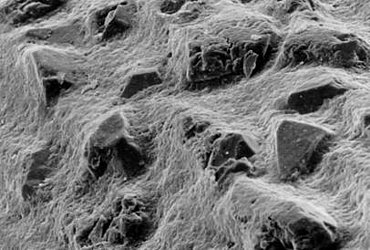
Figure 1: Cooling lubricant contamination [WZL-RWTH Aachen] Figure 2: Abrasive layer [WZL-RWTH Aachen]
f) Cooling lubricant nozzles
A significant effect on the supply of cooling lubricant in line with requirements is the interference resulting from the design of a cooling lubricant nozzle. A proper nozzle supplies the cooling lubricant to the cutting point at any time during the grinding process. This can be done directly, by drawing the jet of cooling lubricant onto the cutting point, or indirectly, by supplying the cooling lubricant to the free pore spaces of the grinding wheel. In both cases, the jet of cooling lubricant must penetrate the air cushion rotating with the grinding wheel and, after penetration, have a sufficiently high jet quality while maintaining a sufficient cooling lubricant velocity. The cooling lubricant discharge velocity is directly related to the peripheral speed of the grinding wheel and results from the cooling lubricant pressure which is adapted to the peripheral speed of the grinding wheel and which must be applied in front of the nozzle. Taking into account the nozzle cross-section, the amount of cooling lubricant flowing through the nozzle is also calculated from this. It is easy to understand that a large nozzle cross-section leads to a low cooling lubricant discharge velocity and also to high cooling lubricant volume flows. Both should be avoided if possible. It should be possible to supply the cooling lubricant jet to the cutting point and/or the grinding wheel topography in a targeted manner and as compactly as possible. Finally, high cooling lubricant volumes also require a correspondingly large cooling lubricant filtration system. In turn, a nozzle outlet opening that is too small can lead to nozzle blockage if the required cooling lubricant purity is not maintained. In general, therefore, it is more complicated to determine a nozzle technology that meets the requirements.
The professional advice of the Grindaix team is available at any time for all questions concerning the design of your cooling lubricant system, your dressing process, your grinding process, your choice of abrasive, the design of cooling lubricant nozzles. We look forward to hearing from you.
g) Air cusion
The grinding wheel as a tool represents a rotating body that enables the formation of an air cushion due to the porosity of its surface. In terms of physics, the phenomenon of boundary layer adhesion occurs here. The relative velocity between the boundary layer near the wheel and the grinding wheel is therefore zero. Using the Navier-Stokes equations, it can be determined analytically that the velocity of the air cushion, directly at the grinding wheel surface consequently corresponds to the circumferential velocity of the grinding wheel and thus to the cutting velocity vc. This is due to the friction between the ambient air and the grinding wheel surface. As the distance from the wheel surface increases, the flow velocity of the air cushion decreases.
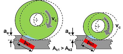
Figure 3: Grinding
Since grinding wheels are usually ceramic bonded, they have a high surface roughness on their entire surface. Therefore, there is a boundary layer adhesion of the ambient air to the entire grinding wheel surface, so that a centrifugal pump effect caused by the rotation occurs. Ambient air is drawn in laterally by the rotating grinding wheel and discharged again in a radial direction via the outer surfaces. The air cushion can be made visible by simple experiments. Figure 4 shows an experimental setup for visualizing the grinding wheel air cushion during surface grinding.
The air cushion rotating with the grinding wheel represents a resistance to the supply of coolant to the grinding wheel or into the grinding gap. Due to the flow forces caused by the air cushion, the cooling lubricant jet may be deflected to such an extent that the grinding wheel surface is hardly supplied. This is inevitably accompanied by a reduced supply of coolant to the grinding gap.
In a research paper on the use of cooling lubricant during grinding with a CBN grinding wheel, this observation is described by T. Beck on the basis of a test at a cutting speed of vc = 100 m/s and a cooling lubricant volume flow QKSS = 50 l/min. The air cushion is also identified here as a resistance for the cooling lubricant jet, which must be overcome for effective cooling lubrication. [1]
Due to the centrifugal pumping effect and the rotation of the grinding wheel, a characteristic flow direction of the air cushion is created, which can be decomposed into different force components using a vector decomposition. Figure 5 schematically shows the force components on the basis of a freely rotating grinding wheel. The lateral inflow of air to the flank of the grinding wheel and the subsequent discharge to the circumferential tool surface can be clearly seen. Significant force components that lead to a deflection of the coolant jet are the x- and the y-component. In the direction of rotation of the grinding wheel, or the vertical (y), a distance-dependent progression of the flow velocities and the flow forces dependent on them can be observed. A variance of the flow velocity also occurs over the grinding wheel width and as a function of the radial distance from the wheel surface. The air cushion thus exhibits a certain morphology with regard to the flow velocities occurring, which depend on the type of grinding wheel used, but also on the circumferential speed vc.
The deflection effects of the cooling lubricant jet by the air cushion can be demonstrated by means of experiments. Figure 6 shows a comparison of two coolant supply conditions in which the air cushion influence is considered with and without an air deflector.
In this test, a deflector plate for the air cushion is installed as a comparison to the non-derived air cushion for the same cutting and cooling lubricant supply parameters. It can be clearly seen that the jet force of the cooling nozzle alone is not sufficient to penetrate the air cushion with the selected supply parameters. Under these circumstances, the grinding gap, as the contact point between the grinding wheel and the workpiece, would not be sufficiently supplied with cooling lubricant without the additional use of a deflector plate.
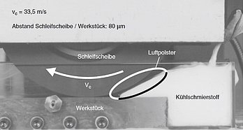
Figure 4: Grinding wheel air cushion during surface grinding [1]
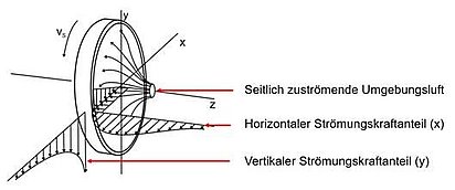
Figure 5: Force decomposition of the air cushion flow [1]
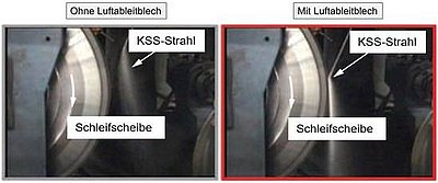
Figure 6: Influence of the coolant jet, without and with air deflector [2]
This and other tests show that there is a factual influence of the air cushion on the cooling lubricant supply. However, Heinzel describes various contrary assessments of the influence of the air cushion on the cooling lubricant supply, based on various cooling lubricant nozzle designs. [3]
- Air cushion influence is controversial and plays a minor role.
- At high cutting speeds (vc ≤ 130 m/s), increasing interference occurs.
- In the case of point-jet nozzles, no disturbance of the jet is to be expected due to high jet velocity.
Irrespective of the above assessments, however, the observed disturbing influence of the air cushion is decisive for countermeasures for air cushion weakening or penetration. Due to the many variable process parameters, starting with the grinding wheel used, the machining process or the cutting speed, there are also variable characteristics of the air cushion with different interference influences on the coolant jet.
Do you have any further questions?
We are always available to answer your questions about our products and services. You can reach us by e-mail at info@grindaix.de or by phone at 02273 95373 0 (weekdays from 8 am - 5 pm).
Sources:
[1] [Beck Thorsten, Berichte aus der Produktionstechnik, Kühlschmierstoffeinsatz beim Schleifen mit CBN, Aachen, Shaker Verlag, 2001, Band 28/2001]
[2] [T.Yoshimi, S.Oishi, S.Okubo, H.Morita. Development of Minimized Coolant Supply Technology in Grinding. JTEKT Engineering Journal English, 2010]
[3] [Heinzel Dipl.-Ing. Carsten; Methoden zur Untersuchung und Optimierung der Kühlschmierung; Bremen; Universität Bremen; 1999]
Relevant products in this article:


These articles from our magazine might also interest you:
Reduce CO2 emissions

Climate change, as described in a very detailed risk research by the European financial institutions, poses an unprecedented challenge to the governance of global socio-economic and also financially acting systems.
Advantages of Coolant Monitoring Systems

Coolant monitoring systems can significantly contribute to increasing reliability and efficiency by collecting and evaluating a wide range of measurement and condition data in the coolant system.
Click here for the article
Lubricoolant protective filtration
The use of cooling lubricants always requires the operation of a filtration system that meets the requirements, because the influence of the purity of the cooling lubricant is considerable. We have therefore compiled a list of what is important in cooling lubricant filtration.
Electromagnetic flow measurement
In electromagnetic flow measurement (EMF), an electrical voltage is generated by the interaction between the flow velocity of a liquid and a magnetic field. This principle is based on Faraday's law of induction.